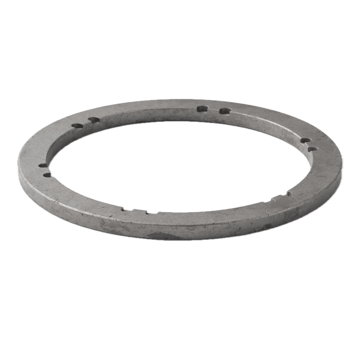
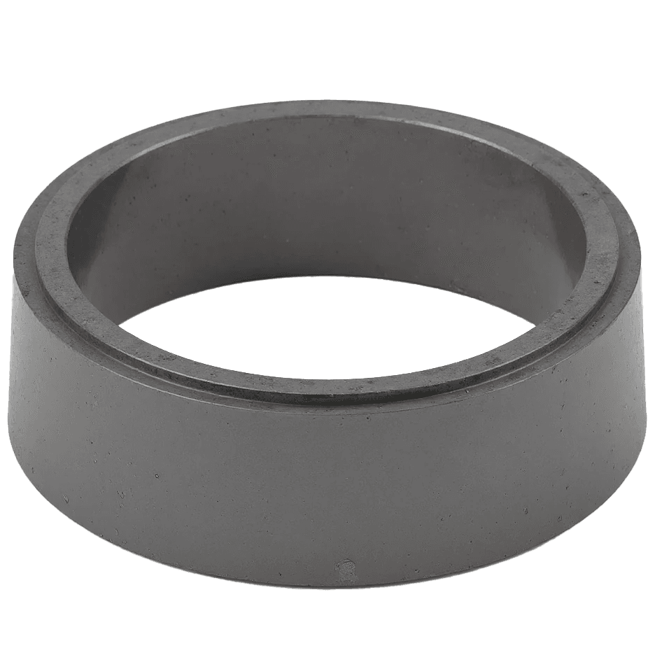
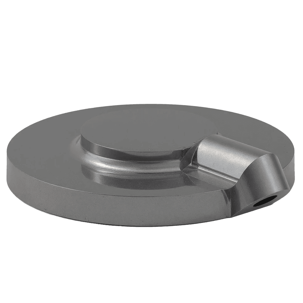
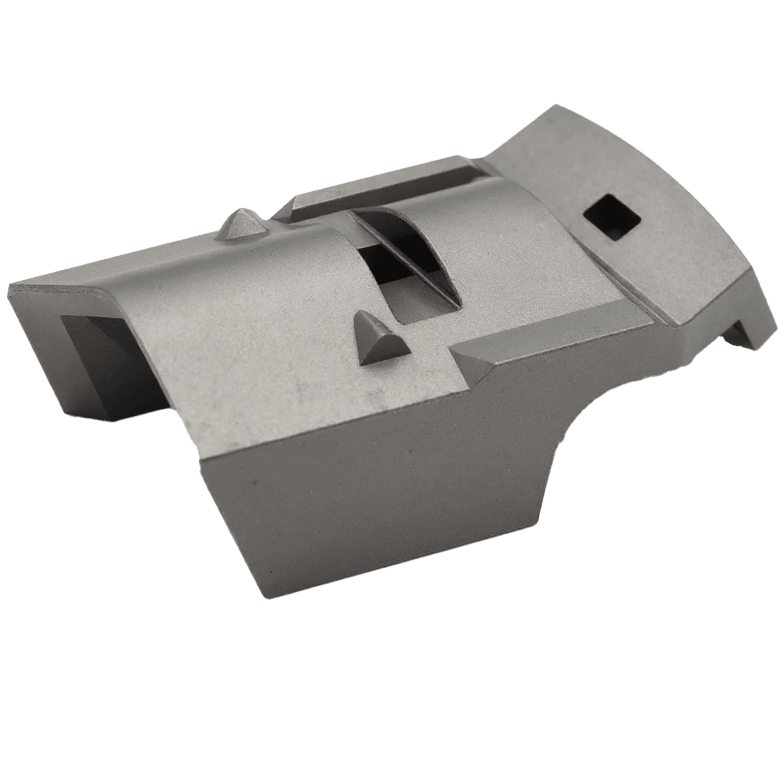
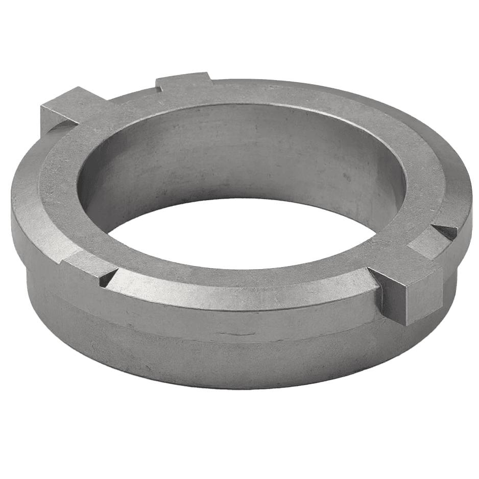
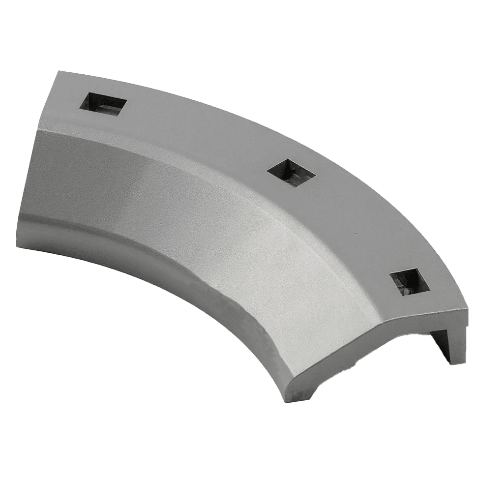
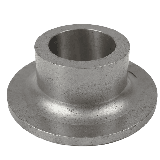
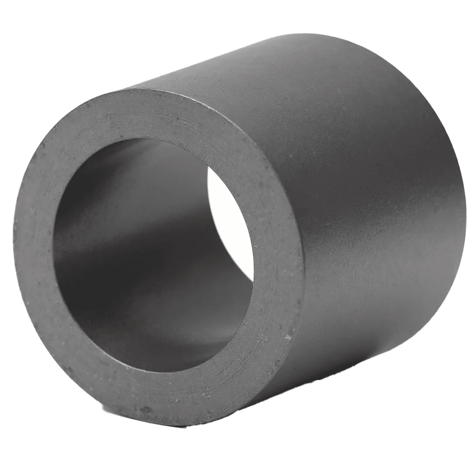
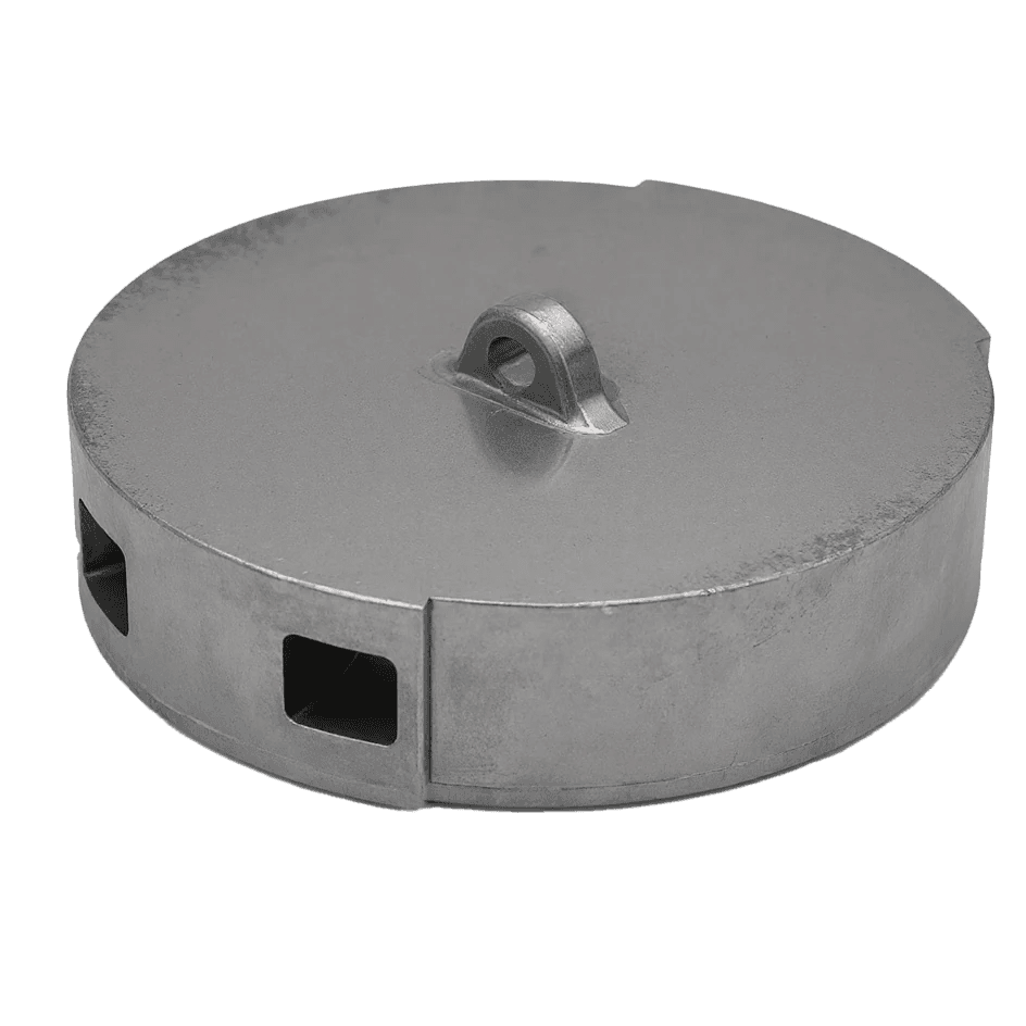
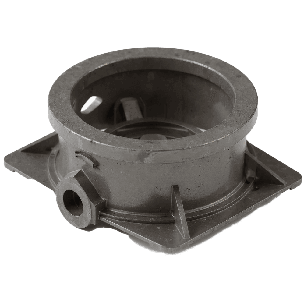
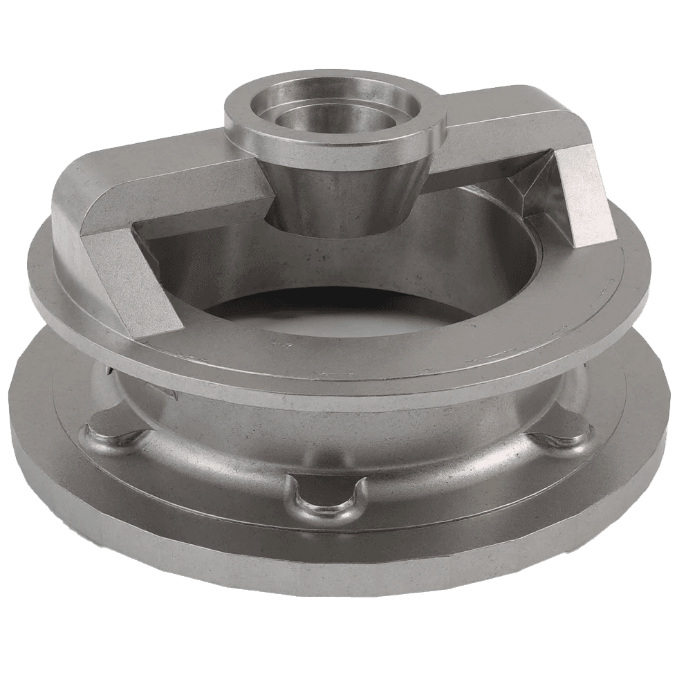
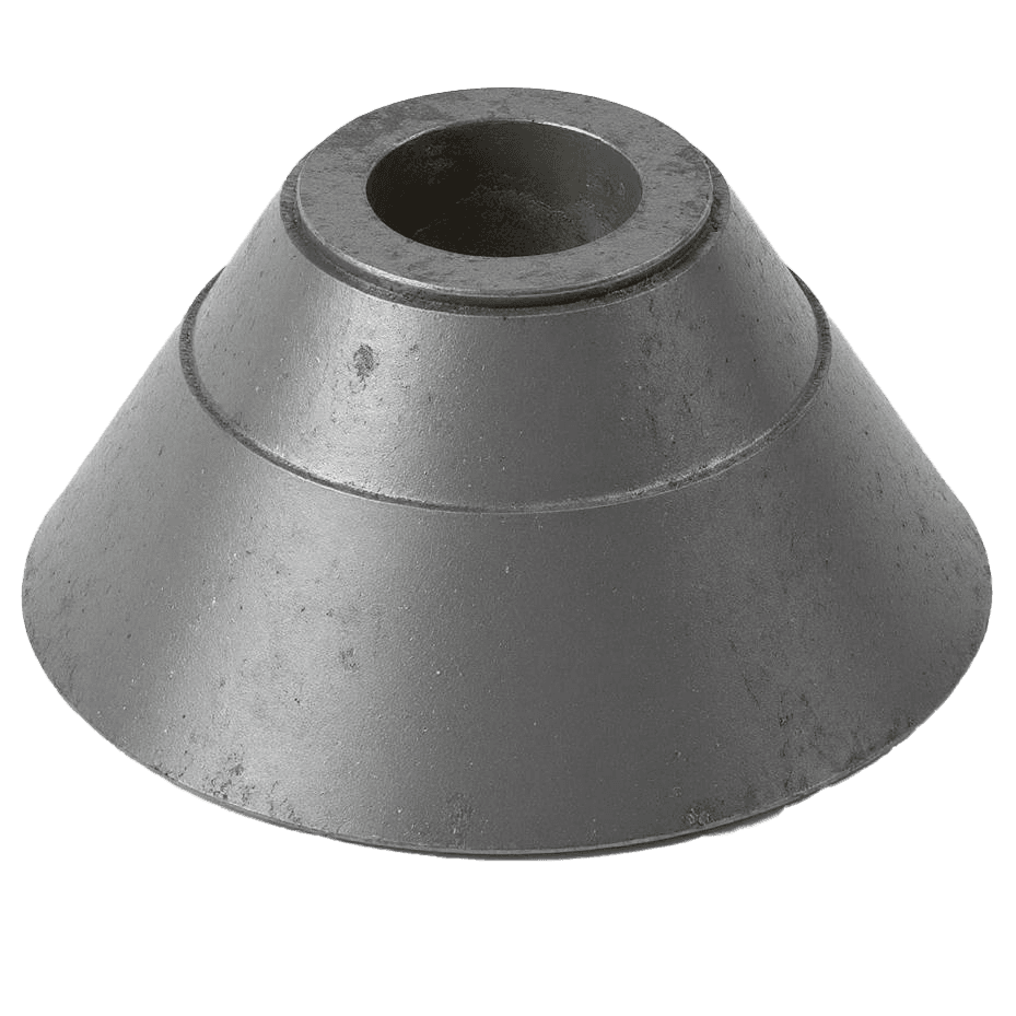
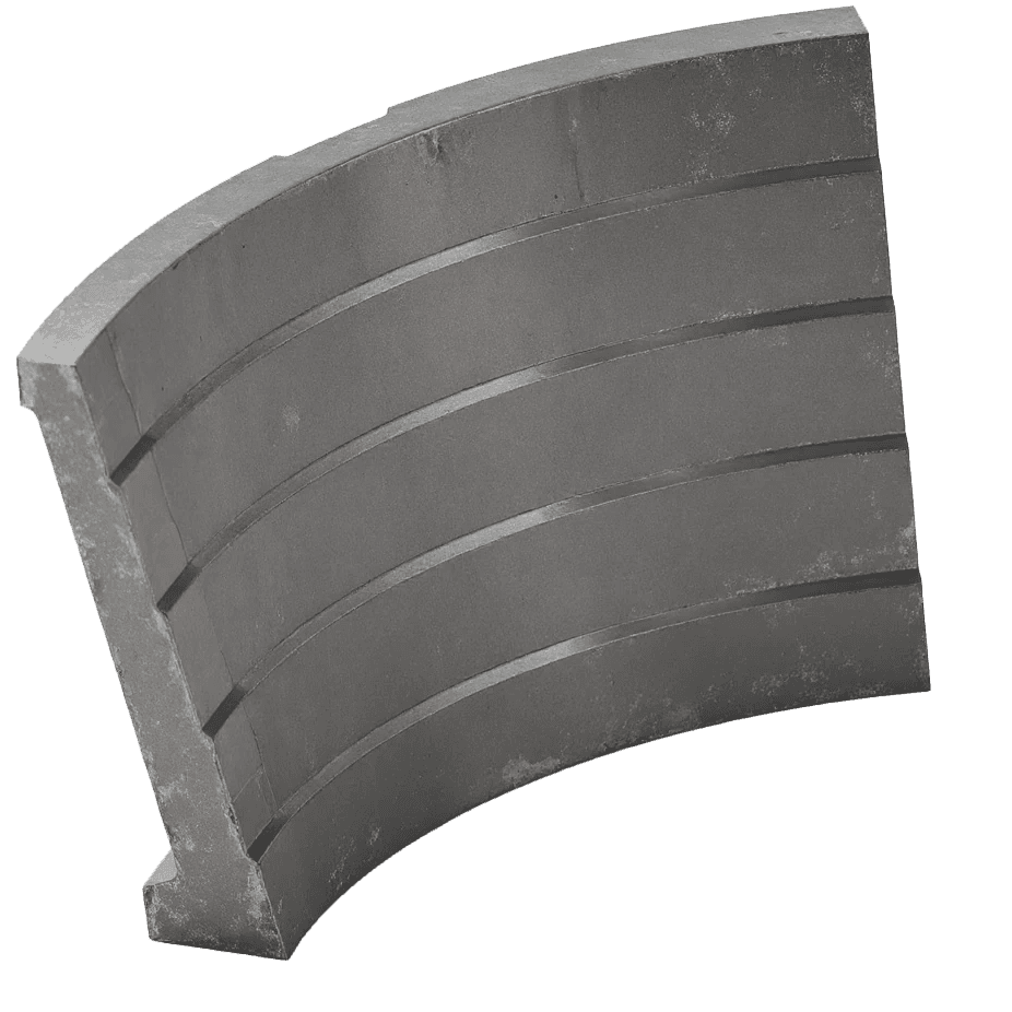
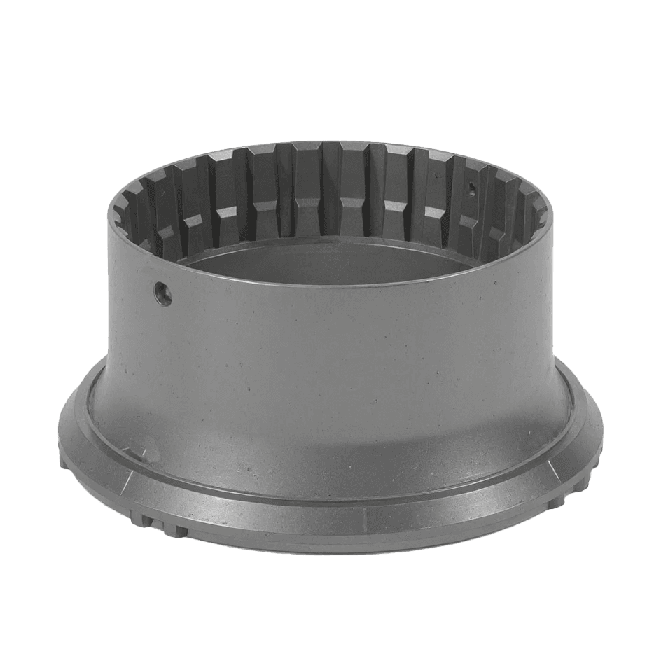
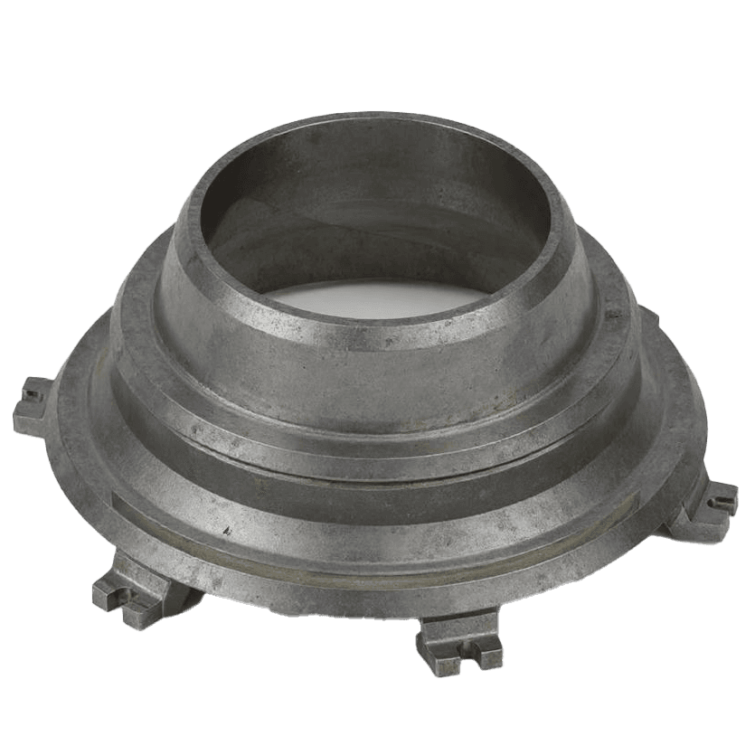
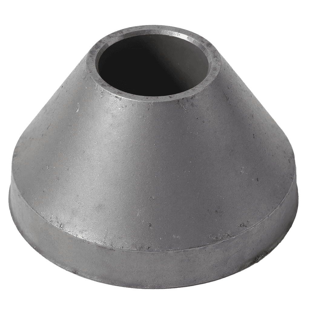
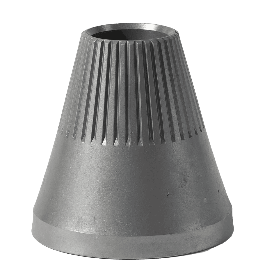
Mazandaran Steel Industries, as the largest and highest-quality producer of crusher machine parts in the country, is proud to manufacture and supply various types of steel components used in cone crushers according to the highest quality standards. Among the products offered are Concave, Mantle, Top Shell, Bottom Shell, Head Center, and other consumable parts for cone crushers, all made using the best raw materials and modern technology to ensure higher durability, efficiency, and service life for our valued customers.
Cone Crushers are among the essential equipment in mining and mineral processing lines. They are primarily used in secondary and tertiary crushing stages, tasked with reducing rock size to dimensions suitable for subsequent processes.
How a Cone Crusher Works
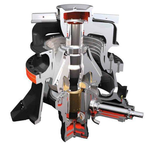
The operation of a cone crusher is based on compression and abrasion. The moving cone (Mantle) rotates and oscillates inside a fixed shell (Concave). Rocks are trapped between the Mantle and Concave and are crushed under pressure.
Process:
- Feeding: Raw materials enter from the top of the machine
- Crushing: Continuous pressure is applied to rocks between Mantle and Concave
- Discharge: Crushed materials exit from the bottom of the machine
These crushers provide uniform product size, high capacity, and low energy consumption, making them superior to other crusher types.
Types of Cone Crushers and Differences
Based on crushing chamber design:
- Standard: For coarse crushing; produces larger output
- Short Head: For finer crushing; steeper cone angle and smaller Mantle-Concave distance
Based on brand and series:
- Metso HP Series
- Sandvik CH Series
- Symons Cone Crusher
Each brand has unique technical features in capacity, liners, internal design, and protection systems.
Due to their ability to produce uniform output, high capacity, and optimized energy consumption, cone crushers are considered one of the key pieces of equipment in the crushing process. Selecting the right model, using the correct Mantle and Concave combination, employing original parts, and regular maintenance directly reduce costs and increase production line efficiency.